
Section 4.2 constraints

The word constraint is used to indicate a device that limits the possibilities of movement of a system of bodies. A generic system, for example a system of rigid bodies, is described by \(n\) parameters, \(q_1, \dots q_n \text{,}\) which are called Lagrangian coordinates of the system or degrees of freedom. In these terms, the generic constraint condition is expressed, in the most generic form, in the following way:

\begin{equation} f\left[q_1, \dots, q_n, \dot{q}_1, \dots, \dot{q}_n, t\right] \leq 0.\tag{4.2.1} \end{equation}

Where, in addition to the Lagrangian coordinates, their derivatives also appear, \(\dot{q}_1, \dots, \dot{q} _n \text{,}\) with respect to time.

For subsequent developments it will be sufficient to consider only fixed (time independent), bilateral (the constraint condition is expressed by the sign of equality), holonomic (independent of velocities) and frictionless (completely allow what they are not constrainig) constraints, that is

\begin{equation} f\left[q_1, q_2, \dots, q_n\right] = 0.\label{constraint_eq}\tag{4.2.2} \end{equation}

Previous equation is generally nonlinear. In the following, we will operate within the framework of 1st order kinematics, therefore we will always operate with linear constraint conditions as described below for the constraints most used in the applications.

Subsection 4.2.1 simple external constraints

Subsubsection 4.2.1.1 roller support

Figure 4.2.1.

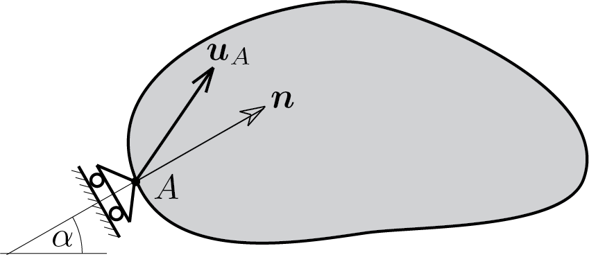
The roller support dictates that the displacement of the point where it is applied can only occur in the direction orthogonal to the axis of the roller support:

\begin{equation} \vec{u}_A \cdot \vec{n} = 0\label{carrello_eq}\tag{4.2.3} \end{equation}

where

\begin{equation*} \vec{u}_A = \left[\begin{array}{c} u_{1A} \\ u_{2A}\end{array}\right] \,, \quad \vec{n} = \left[\begin{array}{c} \cos{\alpha} \\ \sin{\alpha}\end{array}\right] \end{equation*}

In the particular case in which the axis is horizontal, \(\alpha=0\) or \(\alpha=\pi\text{,}\) condition (4.2.3) gives

\begin{equation} u_{1A} = 0\,.\tag{4.2.4} \end{equation}

If the axis is vertical, \(\alpha=\pi/2\) or \(\alpha=-\pi/2\text{,}\) the constraint condition becames

\begin{equation} u_{2A} = 0\,.\tag{4.2.5} \end{equation}

Subsubsection 4.2.1.2 rotation lock

Figure 4.2.2.

This kind of device prescribes the rotation of the application point, i.e.

\begin{equation} \varphi_{A} = 0\,.\tag{4.2.6} \end{equation}

Warning 4.2.3.

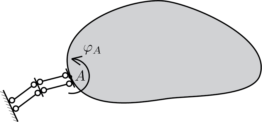
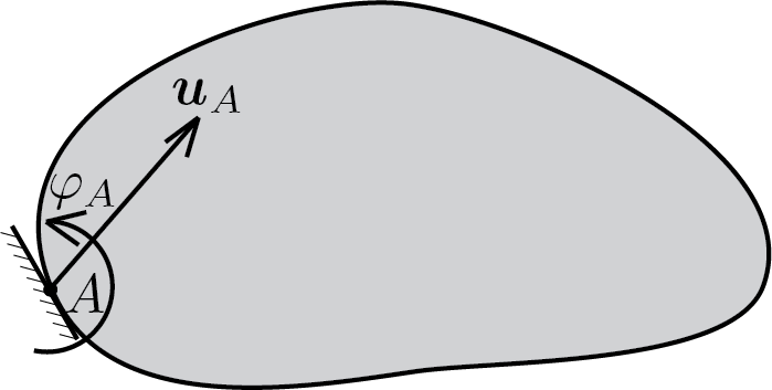
In the case of a rigid body, the rotation cannot vary from point to point and therefore blocking the rotation in one point means blocking it on the whole body. In other words, the point of application of the constraint has no relevance for rigid body kinematics. Anyway it is useful for subsequent developments to maintain the idea to constraint rotation in a particular point of a body.

Subsection 4.2.2 double external constraints

Subsubsection 4.2.2.1 pinned support

Figure 4.2.4.

The pinned support dictates that the displacement of the application point is zero, i.e.

\begin{equation} \vec{u}_A = \vec0\,.\tag{4.2.7} \end{equation}

Subsubsection 4.2.2.2 roller support with rotation lock

Figure 4.2.5.

This kind of device dictates the following conditions

\begin{equation} \begin{split} \vec{u}_A \cdot \vec{n} &= 0 \,,\\ \varphi_{A} &= 0\,. \end{split}\tag{4.2.8} \end{equation}

If the axis of the device is simply horizontal the conditions are

\begin{equation} \begin{split} u_{1A} &= 0 \,,\\ \varphi_{A} &= 0\,. \end{split}\tag{4.2.9} \end{equation}

If the axis is vertical the constraining conditions are

\begin{equation} \begin{split} u_{2A} &= 0 \,,\\ \varphi_{A} &= 0\,. \end{split}\tag{4.2.10} \end{equation}

Subsection 4.2.3 triple external constraints

Subsubsection 4.2.3.1 fixed support

Figure 4.2.6.

Finally the fixed support dictates

\begin{equation} \begin{split} \vec{u}_A &= \vec{0} \,,\\ \varphi_{A} &= 0\,. \end{split}\tag{4.2.11} \end{equation}

Subsection 4.2.4 internal constraints

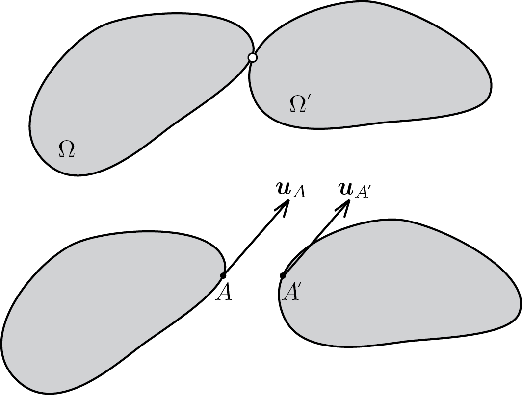
The connection of two or more rigid bodies can be made by means of devices called internal constraints. By way of example, avoiding reviewing all possible cases, only one of the most recurrent cases is discussed.

Subsubsection 4.2.4.1 internal hinge

Figure 4.2.7.

The constraint conditions can be expressed as follows

\begin{equation} \vec{u}_{A} = \vec{u}_{A'}\,.\tag{4.2.12} \end{equation}