Section 5.3 constraints
A body or system of bodies is typically subjected to both applied loads and assigned constraint conditions. From a static point of view, the constraints are treated by representing the action exerted by the constraint in terms of forces or torques called constraint reactions. This procedure, as we will see, allows to obtain the free body diagram through which the body is represented under the action of two groups of static entities: the applied actions and the constraint reactions.
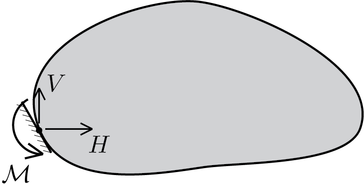
In the 2D case, in general, an applied constraint can give rise to 3 reaction components:
\begin{align*}
H \amp\quad \text{horizzontal component,}\\
V \amp\quad \text{vertical component,}\\
\mathcal{M}\amp\quad \text{torque component.}
\end{align*}
The presence, in a point of the body, of all 3 components or only some of them depends on the type of constraint applied.
Subsection 5.3.1 absence of constraint
It is the trivial case in which at a point there is no constraint applied, consequently it will not be possible to have any reaction component different than zero:
\begin{equation}
H=0 \,, \quad V=0 \,,\quad \mathcal{M} = 0\,.\tag{5.3.1}
\end{equation}
Subsection 5.3.2 simple constraints
Subsubsection 5.3.2.1 roller support
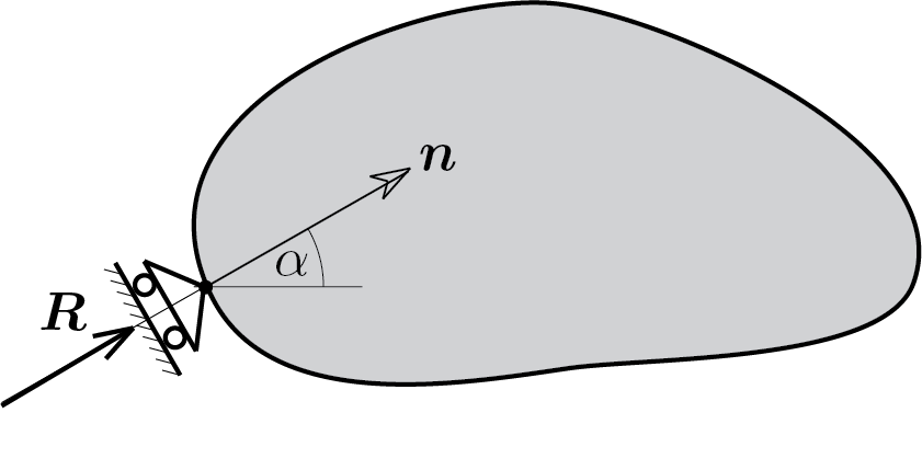
The presence of the roller support determines, from the static point of view, only a reaction force, \(\vec{R} \text{,}\) directed according to the axis of the roller support. Then, of the three reaction components, only the first two can be different from zero
\begin{equation}
H \neq 0 \,, \quad V \neq 0 \,,\quad \mathcal{M} = 0\,.\tag{5.3.2}
\end{equation}
Furthermore, the direction of the reaction force is known and therefore the two components \(H \) and \(V \) are not independent of each other but linked by the relationship
\begin{equation}
\frac{V}{H} = \tan{\alpha}\,.\tag{5.3.3}
\end{equation}
Obviously if the roller support has a horizontal axis only \(H \) can be different from zero:
\begin{equation}
H \neq 0 \,, \quad V = 0 \,,\quad \mathcal{M} = 0\,.\tag{5.3.4}
\end{equation}
In the case of vertical axis
\begin{equation}
H = 0 \,, \quad V \neq 0 \,,\quad \mathcal{M} = 0\,.\tag{5.3.5}
\end{equation}
Subsubsection 5.3.2.2 rotation lock
This constraint blocks the rotation of the body making possible only a non zero torque component. Therefore in the point of application of the constraint it is possible to have
\begin{equation}
H = 0 \,, \quad V = 0 \,,\quad \mathcal{M} \neq 0\,.\tag{5.3.6}
\end{equation}
Subsection 5.3.3 double constraints
Subsubsection 5.3.3.1 hinge support
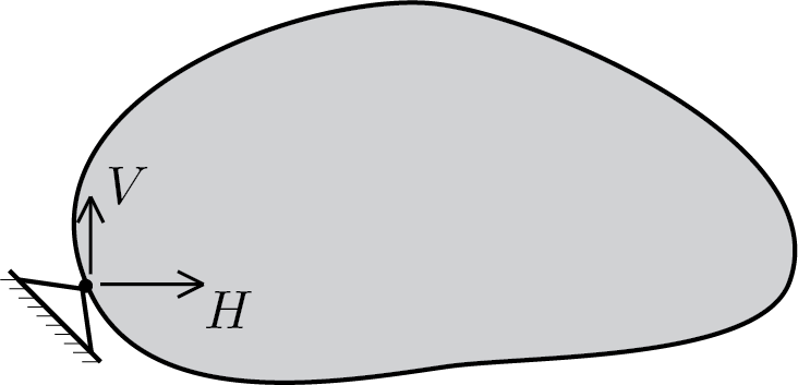
The presence of the hinge support can be read as a reaction force \(\vec{R} \) whose direction is not known a priori, as in the case of the roller support. Therefore we will have the two reaction components, horizontal and vertical, possibly non-zero and independent
\begin{equation}
H \neq 0 \,, \quad V \neq 0 \,,\quad \mathcal{M} = 0\,.\tag{5.3.7}
\end{equation}
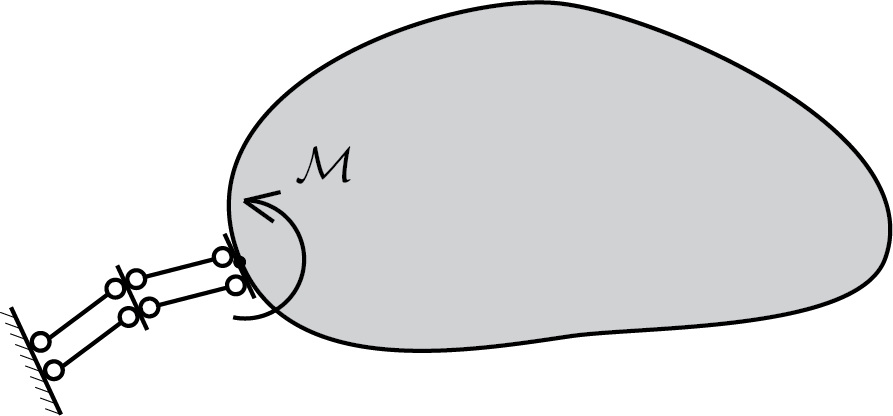
Subsubsection 5.3.3.2 roller support with rotation lock
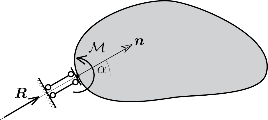
This device acts like a roller support and also, because of the constrained rotation, exerts a torque. Therefore the reaction components can be described as follows
\begin{equation}
H \neq 0 \,, \quad V \neq 0 \,,\quad \mathcal{M} \neq 0\,,\tag{5.3.8}
\end{equation}
where
\begin{equation}
\frac{V}{H} = \tan{\alpha}\,.\tag{5.3.9}
\end{equation}
Also for this device if the axis is horizontal only \(H \) can be different from zero:
\begin{equation}
H \neq 0 \,, \quad V = 0 \,,\quad \mathcal{M} \neq 0\,.\tag{5.3.10}
\end{equation}
and in the case of vertical axis
\begin{equation}
H = 0 \,, \quad V \neq 0 \,,\quad \mathcal{M} \neq 0\,.\tag{5.3.11}
\end{equation}
Subsection 5.3.4 triple constraints
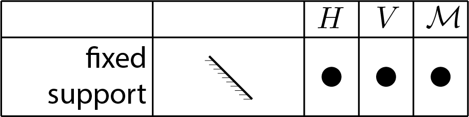
Subsubsection 5.3.4.1 fixed support
With the fixed support the constraint can react through all the three components which are independent from each other
\begin{equation}
H \neq 0 \,, \quad V \neq 0 \,,\quad \mathcal{M} \neq 0\,.\tag{5.3.12}
\end{equation}
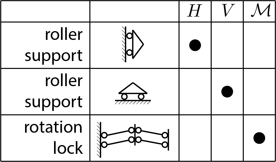
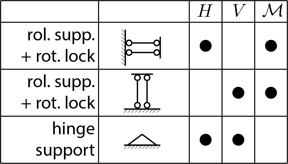
Subsection 5.3.5 summary
The following figures illustrate for the 2D case the graphic representation of the constraints and the possible presence of the reaction components \(H \text{,}\) \(V \) and \(\mathcal{M} \text{.}\)
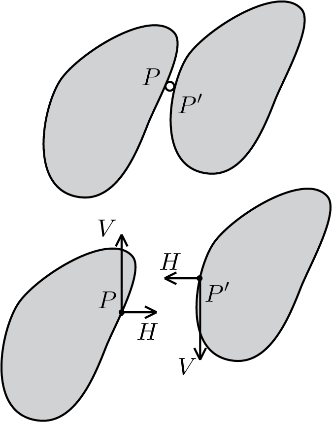
Subsection 5.3.6 internal constraints
Unlike external constraints, internal constraints prescribe kinematic conditions at the points of contact between one or more bodies. Therefore, from a static point of view, they are treated in terms of constraint reactions exchanged by the bodies affected by the constraint condition. The figure shows one of the most recurring cases, namely the case of the internal hinge.